How Far Can a Solar Extension Cable Be?
- Walid
- 4 hours ago
- 10 min read
Clear answer (right up front): There’s no single universal “maximum length” for a solar extension cable. In real systems, your maximum usable distance is set by two limits: ampacity (can the wire safely carry the current without overheating?) and voltage drop (will the cable distance cause enough PV voltage loss to reduce charging performance?). For most DIY solar designs, you aim for an acceptable voltage drop (commonly a few percent) and then size the cable (wire gauge) to keep both constraints satisfied.

Key Takeaways
Solar extension cable length is limited by two things: heat (ampacity) and performance (voltage drop).
Voltage drop grows with distance and current, and it’s worse on thinner wire.
Thicker copper (e.g., 8 AWG vs 12 AWG) can support longer runs with less performance loss.
MC4 extension cable “compatibility” matters: wrong connectors, poor seals, or loose mating can create heat and failures.
The best process is: (1) confirm wire ampacity, then (2) calculate voltage drop, then (3) pick the longest run you can support safely.
What Limits Solar Extension Cable Length?
Ampacity (heat) vs voltage drop (performance)
Think of cable length like a double constraint:
Ampacity / current capacity (safety)Even if the wire “works,” the insulation and conductor must handle the current. If you under-size the cable, it can overheat under sustained load. This is especially relevant if your system can generate higher current than the cable rating assumes.
Voltage drop (efficiency)Solar cables are DC power transmission lines. DC wiring has electrical resistance, so current flowing through the conductor causes a voltage drop. The further the distance, the higher the resistance losses—meaning the controller/inverter may receive a lower voltage than the panels produce at the roof/array.
Result: You can sometimes have a cable that is “ampacity-safe” but still “voltage-drop-inefficient,” causing slower charging or reduced system performance.
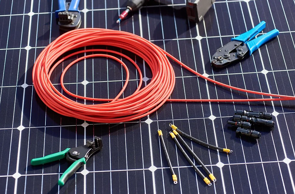
What Is a Solar Extension Cable?
A solar extension cable is typically a PV-rated cable used to extend the connection between components in a PV system—most commonly between:
a solar panel and an MC4-compatible junction,
multiple panels wired in series/parallel (string/array wiring),
a panel and a charge controller/inverter input (in off-grid/RV systems),
or rooftop array wiring to a combiner/entry point.
Most solar extension cables use:
UV/weather-resistant insulation designed for outdoor use,
PV connector compatibility (often MC4 and compatible variants),
and conductor sizes (wire gauges) meant for the PV current levels.
Why PV Cable Distance Affects Performance
When your PV panels produce power, the current and voltage reaching the next device (charge controller, inverter, combiner) depend on the electrical pathway. In longer runs, resistance in the cable reduces the effective voltage delivered—so the system efficiency drops.
A useful way to think about it:
Higher voltage systems can tolerate distance better (percentage drop matters less), if current isn’t too high.
Higher current systems penalize distance more, because voltage drop increases roughly in proportion to current.

Understanding Voltage Drop in Solar Wiring
What “solar panel voltage loss” actually means
Voltage drop is the reduction in voltage along the conductor due to its resistance when current flows.
In PV DC circuits, voltage drop can affect:
how much power the controller/inverter can accept,
the operating point of MPPT (maximum power point tracking),
and in some setups, the threshold behavior of connected electronics.
Important: Voltage drop is usually more noticeable in low-voltage systems (like some RV/off-grid setups at 12V/24V battery charging stages) and in high-current scenarios.
Maximum Recommended Solar Cable Lengths
Because every installation differs (panel power, wiring layout, current, voltage level, wire gauge, temperature, connector condition), there is no single maximum length that works for everyone.
But you can use two practical ideas:
Use ampacity as the “must not exceed” safety rule.
Use voltage drop as the “don’t exceed” performance rule.
Practical rules of thumb (with explicit assumptions)
For DIY planning, a common approach is to keep voltage drop to something like a few percent on the DC run. If you don’t want to guess, calculate it—because “a few percent” still depends on:
current in amps,
one-way distance, and
conductor resistance (wire gauge + material).
Solar Cable Length Chart by Wire Gauge (Examples)
Below are example-based length estimates to help you choose an initial wire gauge. These are NOT universal limits—they’re a planning tool under clear assumptions.
Assumptions used in the examples
Copper conductors
DC circuit
Voltage drop target: about 3% of PV voltage
Current: 8A or 10A (typical ballpark for small arrays; exact current depends on panel power and operating voltage)
One-way length listed (cable run from panels to controller/entry point)
Because exact results depend on actual voltage, current, insulation temperature, and the cable’s published resistance, treat these as starting estimates. Use the calculation method below for accuracy.
Example planning chart (copper, ~3% voltage drop target)
Wire gauge (AWG) | Example current | Approx. “comfortable” one-way length |
12 AWG | ~8A | ~8–12 meters (about 25–40 ft) |
12 AWG | ~10A | ~6–10 meters (about 20–33 ft) |
10 AWG | ~8A | ~12–18 meters (about 40–60 ft) |
10 AWG | ~10A | ~10–15 meters (about 33–50 ft) |
8 AWG | ~8A | ~18–28 meters (about 60–90 ft) |
8 AWG | ~10A | ~15–24 meters (about 50–80 ft) |
If your target voltage is higher (string voltage higher), you often gain tolerance; if your current is higher, your usable distance drops.
Featured-snippet-ready guidance:
If you’re unsure, the fastest path is: choose a cable gauge that comfortably meets ampacity, then calculate voltage drop for your exact current and distance.

10 AWG vs 12 AWG vs 8 AWG: What Changes at Distance?
Why thicker wire matters
Wire gauge affects electrical resistance:
Thinner wire (higher AWG number) → more resistance → more voltage drop for the same current and distance
Thicker wire (lower AWG number) → less resistance → less voltage drop
This is why many “long run” solutions use larger wire gauges like:
10 AWG instead of 12 AWG,
8 AWG when distance and current are both significant.
A simple decision rule
If your run is short and current is moderate → 12 AWG might be fine.
If your run is medium-to-long or you expect higher current → step up to 10 AWG.
If you need very long runs and want to protect performance → 8 AWG (or larger), plus careful connector practices.
How to Calculate Voltage Drop (Step-by-Step)
The concept (DC voltage drop)
A common approximation for DC voltage drop uses conductor resistance and the fact that current travels to the load and back through the circuit.
A practical formula many calculators follow is conceptually:
Voltage drop = current × (conductor resistance per unit length × total circuit length)
Because the circuit includes the return path, many tools use a factor of 2 for one-way length on a two-conductor DC run.
What you need
To calculate voltage drop, collect:
Current (I) in amps on the extension run
One-way distance (L) in feet or meters
Cable resistance per unit length (from the cable spec sheet or manufacturer documentation)
System voltage reference for percentage (e.g., PV operating voltage at Vmp, or the voltage relevant to the controller/inverter input)
If your cable manufacturer provides resistance per 1000 ft (or per meter), use that. Otherwise, rely on published resistance values for the exact cable type and temperature rating.
Quick worksheet method (what to do)
Determine the operating current you expect in the extension (based on PV power and system design).
Pick the correct wire gauge/material for that current.
Get conductor resistance from the cable specs.
Compute voltage drop with your tool/formula.
Convert to percentage:
Voltage drop % = (Vdrop ÷ reference voltage) × 100
Compare to your target threshold (often “a few percent,” but the right threshold depends on system design goals).
If you want a practical threshold
Many designers aim to keep DC voltage drop relatively low to protect power delivery and MPPT operation. Without quoting a universal code rule for PV DC extension runs, the safest recommendation is:
Calculate it, and
keep it within a conservative “few percent” target unless your system explicitly tolerates more.
Solar cable voltage drop calculator
If you’d rather not calculate resistance manually, use a voltage drop calculator—but ensure it uses the correct conductor material, temperature, and cable resistance. Some general calculators assume household AC wiring and won’t match PV cable behavior.
External-source placeholder (optional): consider linking to a reputable voltage drop calculator or manufacturer application note if you have one.
Best Cable Lengths for Common Setups
RV Solar Systems (typical focus: portable arrays to controller)
In RV and portable use, extension cables are common because panels may mount on awnings/rooftops while the controller is inside.
Planning tips:
Keep runs as short as practical.
If you can choose wiring layout: place the controller closer to the array when possible.
If you’re extending MC4 cables to reach a longer rooftop/awning distance, prioritize wire gauge (10 AWG or 8 AWG often helps when distances grow).
Off-Grid Cabins (controller/inverter often farther from arrays)
Off-grid systems often run DC farther across yards, rooftops, or shed-to-house pathways.
Planning tips:
Verify whether you’re extending from panels to charge controller (PV DC) or from batteries to inverter (low-voltage DC/high-current).
The “best wire length” differs drastically depending on whether the current is high (inverter/battery side) or moderate (PV string side).
Rooftop Solar (extensions to combiner/entry points)
On rooftops, you might extend between:
panel wiring and combiner,
string wiring and roof penetrations,
or sub-array junctions.
Planning tips:
Use PV-rated cable with UV endurance and proper routing.
Treat connector integrity and strain relief as essential—loose MC4 connections can create localized heating.
Portable Solar Panels (camping/charging banks)
Portable setups can be forgiving because you’re often using smaller currents or temporarily operating systems.
Planning tips:
Avoid “extension cable sprawl.” Every additional connection adds resistance and potential failure points.
Use the fewest joins possible and keep cable runs away from abrasion.
How to Reduce Voltage Loss in Long Runs
If your distance is fixed and you still want strong performance, you have three practical levers:
1) Increase wire gauge
Thicker wire reduces resistance, which reduces voltage drop. This is the most straightforward fix.
2) Reduce current (design choice, not a cable trick)
Voltage drop scales with current. If you can change how panels are connected (stringing configuration) to increase operating voltage or reduce current on a given run, voltage loss can improve. This is usually a design-level decision.
If you change string configuration, verify compatibility with your charge controller/inverter MPPT ranges and safety constraints.
3) Shorten the “extended” portion
Sometimes you can move the controller position, adjust panel placement, or reconfigure junctions to reduce the run length you need to extend.
Copper vs Aluminum Solar Cables
Copper solar cable
Copper is popular for PV extensions because it’s:
straightforward in small DIY runs,
flexible and easy to terminate (depending on connector),
and typically offers lower resistance per gauge compared to aluminum.
Aluminum photovoltaic cable extension
Aluminum can be used in many electrical contexts, but in PV extensions you must be careful because:
aluminum often requires a larger conductor size to match resistance performance,
termination practices must be correct to avoid overheating at lugs/connectors,
and you must follow the termination instructions specific to the connector system you use.
Rule of thumb: If you’re not set up for aluminum termination discipline, copper is usually the safer DIY path.
MC4 Extension Cable Considerations
Connector compatibility and contact reliability
When people ask “how far can I run a solar extension cable,” they often underestimate connector issues.
If you use MC4 extension cable, check:
connector family compatibility (some MC4 variants are not interchangeable),
the connector’s temperature and weather rating,
that mating pairs fully click/lock.
Why it matters: Partial contact can increase resistance at the connector. That can cause heating and further voltage drop.
Weatherproofing and mechanical strain
Outdoor PV connections must handle:
rain/UV exposure,
temperature cycling,
and mechanical loads (wind, cable tugging).
Practical advice:
Use proper routing and strain relief so connectors aren’t bearing weight.
Keep cable ends sealed if the system includes protective caps.
Avoid bending connectors tightly at sharp angles.
If your extension includes inline connectors or junction boxes, confirm the whole assembly is intended for outdoor DC use.
NEC & Solar Wiring Safety Standards (What to Follow)
Solar PV wiring isn’t “one-size-fits-all.” Safety depends on system voltage, environment, and installation method.
In the United States, PV wiring requirements are generally covered by the NEC (notably Article 690 for PV systems and Article 310 for conductors).
Your local jurisdiction may have additional requirements.
Always follow the manufacturer installation instructions for cables/connectors and any inverters/controllers.
Professional guidance: If you’re unsure, consult a qualified solar installer or electrician. This is especially important if you’re extending beyond typical DIY lengths or working near higher-voltage PV strings.
(External-source placeholder: link to relevant NEC section summaries or a local authority document if your site includes code resources.)
Common Solar Wiring Mistakes
These mistakes don’t just reduce performance—they can create safety or reliability problems:
Under-sizing the wire gauge for the current and distance
Assuming connector resistance is negligible (it isn’t)
Using non-PV extension cables or indoor-only cable outdoors
Mismatching MC4 connector types or using poor-quality adapters
Loose or partially seated connectors that heat up over time
Ignoring polarity (DC errors can damage equipment)
Routing cables where abrasion or UV damage occurs
Avoiding strain relief, letting connectors take mechanical stress
FAQs
1) How long can a solar panel extension cable be?
You can’t give one universal number because distance limits depend on wire gauge, current, and acceptable voltage drop. Use ampacity for safety and calculate voltage drop for performance. As a planning starting point, thicker copper like 10 AWG or 8 AWG supports longer runs than 12 AWG, especially at higher current.
2) What is the maximum length for a solar extension cable?
“Maximum” is really two maxima:
a safety maximum based on ampacity (wire rating and installation conditions), and
a performance maximum based on voltage drop.
If your voltage drop becomes too high, the system’s power delivery can suffer even if the wire stays within ampacity.
3) How far can you run solar panel wires?
The practical answer is: run them as far as your system can tolerate voltage drop while remaining within ampacity and using PV-rated cable/connectors. If you must run long distances, reduce current (system configuration), increase wire gauge, and minimize connector count.
4) Is there an MC4 solar extension cable distance limit?
There’s no universal “MC4 distance limit,” but longer runs increase the electrical and mechanical demands. Also, connectors can become a limiting factor if compatibility, sealing, or mating is imperfect. The real limiter is usually voltage drop plus connector reliability.
5) What’s the best wire size for long solar cable runs?
In general terms, longer runs call for larger wire gauges (smaller AWG number) to reduce resistance and voltage drop. The “best” size depends on your current and distance—calculate voltage drop to pick the correct gauge rather than guessing.
6) How do I reduce voltage drop in solar systems?
Common methods include:
upgrading to a thicker cable,
shortening cable runs where possible,
optimizing PV wiring configuration to reduce current on the extended run,
and using reliable PV connectors with good strain relief.
Final Thoughts
So—how far can a solar extension cable be?Far enough to meet two requirements: safe current capacity and acceptable voltage drop. If you treat extension length as a purely “connector length” problem, you’ll miss the real performance limiter: resistance losses over distance.
If you want a reliable buying and planning approach, do this:
Confirm the wire gauge can handle expected current (ampacity).
Calculate voltage drop for your exact distance and system voltage.
If voltage drop is too high, move up to a thicker gauge and reduce connector count/strain.
Do that, and you’ll get a solar setup that performs consistently—not just one that “connects.”


Comments