How Material Selection Affects PV Connector Safety: A Complete Guide for Solar Applications
- Walid
- Apr 29
- 7 min read
PV connector safety isn’t only about “meeting a rating on a datasheet.” In real systems, safety outcomes are strongly influenced by which materials are used for contacts, insulation, housings, seals, and mechanical retention parts—and how those materials behave under heat, moisture, UV, vibration, and long-term aging.

Key Takeaways
PV connector safety is driven by materials that control contact heat, corrosion, insulation aging, and sealing integrity.
Contact/terminal materials + plating strongly affect long-term contact resistance and the risk of hot spots.
Polymer housing and insulation determine resilience to UV, thermal cycling, and chemical exposure from the environment.
Seals and overmolding determine how well the connector resists water ingress and contamination.
Use a materials verification checklist: don’t rely on appearance or “fit.”
Quick Answer: Which materials most affect PV connector safety?
If you want the short list, prioritize:
Contact materials & plating These determine how reliably current transfers over years of vibration and temperature cycles.
Insulation and housing polymers These determine whether the connector body and insulation maintain mechanical integrity and dielectric properties after UV/heat aging.
Sealing compounds and interfaces These determine whether moisture and contaminants enter and undermine insulation performance or corrosion performance.
Retention components (springs, latches) and conductive parts These determine whether the connector stays securely mated under thermal expansion and mechanical stress.
The real safety risks PV connectors must withstand
Heat and contact resistance
One of the most common PV connector safety concerns in the field is localized heating caused by increased contact resistance at terminals or mating interfaces.
Material-related causes typically include:
contact surfaces that degrade (oxidation/corrosion),
plating that wears or fails to protect,
contact geometry or spring force that doesn’t stay stable,
connector materials that deform (“creep”) and reduce contact pressure over time.
Once contact resistance rises, the connector can run hotter, which accelerates polymer aging and can increase the risk of unsafe thermal degradation.
Corrosion and galvanic effects
Coastal environments, polluted air, and cleaning chemicals can expose connectors to conductive contaminants. Material choice matters because:
some metal combinations cause galvanic corrosion when dissimilar metals are in contact with moisture/electrolytes,
poor corrosion resistance leads to surface roughening and higher resistance,
corrosion products can also compromise sealing surfaces and mechanical retention.
UV exposure and polymer aging
PV connectors are outdoors. UV exposure can embrittle plastics, causing:
cracks in housings,
hardening of seals,
loss of mechanical strength,
reduced strain relief performance.
Thermal cycling (hot to cold) then worsens mechanical stress, and connectors can become more sensitive to vibration and flexing.
Water ingress and insulation breakdown
Moisture intrusion can create two classes of risk:
electrical risk: moisture contamination can lower insulation resistance and increase leakage paths.
chemical/mechanical risk: water supports corrosion at interfaces and can compromise sealing.
Sealing and overmolding materials must be compatible with expected thermal cycles and remain elastic enough to maintain a robust seal.
Mechanical stress, vibration, and creep
In many installs, connectors experience repeated stress from:
wind vibration,
roof movement,
cable weight and strain relief behavior,
installation handling and cable bend radius.
Material creep (slow deformation under constant stress) can reduce contact pressure, causing heat to increase over time.
Material categories that drive connector performance (and safety)
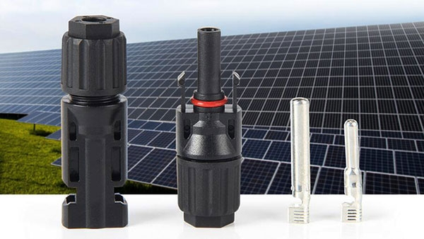
1) Contact/terminal materials (metal “heart” of safety)
The connector’s conductive parts must:
resist corrosion over years,
maintain stable contact pressure,
avoid creating excessive galvanic interactions,
remain compatible with the termination method (crimp, solder, or other).
A safe connector isn’t just “conductive.” It must be stable under cycling. Materials that are soft, corrosion-prone, or poorly protected tend to become less reliable.
2) Plating and surface treatment
Plating is often where long-term safety is won or lost. Surface treatment can:
protect against oxidation and corrosion,
improve wetting/compatibility for mating interfaces,
reduce friction and maintain consistent contact behavior.
If plating thickness, coverage, or adhesion is inadequate, you can see gradual degradation:
contact resistance rises,
heat increases,
insulation aging accelerates.
3) Insulation and housing polymers
Connector bodies and insulation must handle:
UV exposure,
temperature cycling,
mechanical impacts (handling, installation),
long-term chemical exposure (pollution + cleaning residues).
The “right polymer” typically depends on your environment. A housing that performs well in controlled lab conditions may still degrade faster in coastal humidity or high-UV regions.
4) Seals, gaskets, and potting/overmolding
Seals are not just “rubber rings.” They also:
maintain elasticity over thermal cycles,
resist chemical swelling or hardening,
prevent water ingress at junction points.
Pay special attention to sealing materials at:
cable entry points,
mating interface boundaries,
any interface where contamination could reach insulation surfaces.
5) Screws, springs, and retention components
Even if electrical materials are perfect, retention hardware can fail safety goals if it loosens or loses spring force.
Materials and coatings for springs/latches should resist:
corrosion,
fatigue,
stress cracking.
Retention stability keeps contact pressure consistent—one of the critical drivers of long-term connector temperature rise.
Failure-mode → material-cause map (featured-snippet ready)
Use this “quick triage” to understand what to ask your supplier.
Safety risk you’re worried about | Common symptom | Material areas that most influence it | What to request/verify |
Hot spots / heating | Warm connector, discoloration, periodic faults | Contact metal + plating, spring force materials, polymer creep | Evidence of contact resistance stability, corrosion tests, thermal cycling results |
Corrosion-related failure | Green/white deposits, higher resistance, intermittent faults | Contact metallurgy (dissimilar metals), seal materials, exposed interfaces | Corrosion resistance test evidence and salt/contamination exposure suitability |
UV cracking / embrittlement | Brittle housings, cracked strain relief | Housing polymer, seal polymer compatibility | UV aging/durability evidence and housing mechanical retention after aging |
Water ingress | Moisture inside, leakage/performance drift | Seals/overmolding compounds, entry seals, connector interface design | Water ingress resistance evidence under realistic conditions |
Mechanical loosening | Poor mating, intermittent contact, connector damage | Latches/springs, cable strain relief design | Mating retention tests, vibration/handling durability evidence |
Tip: If a supplier can’t clearly connect their materials to the risk you’re targeting, your safest move is to require evidence and/or perform acceptance checks for your project environment.
What to verify in supplier documentation
Below is a practical checklist you can apply during procurement or engineering review. It’s designed to be evidence-led rather than spec-sounding.
Evidence of electrical performance stability over time
Ask for documentation that demonstrates:
stable contact behavior under mating and unmating cycles (if applicable),
stable electrical performance under temperature cycling,
termination integrity compatibility (e.g., crimp specification alignment with the connector terminals).
If you can only obtain initial test reports, request follow-up evidence for aging or accelerated durability where relevant.
Evidence of environmental durability (UV, moisture, heat)
Your connector materials should be validated for your environment. Request:
UV exposure / polymer aging testing evidence,
moisture or water ingress resistance evidence,
thermal cycling durability evidence (hot/cold swings),
corrosion resistance evidence appropriate to site conditions.
If your project is coastal or polluted, ensure the supplier’s durability testing is representative. If not, request additional project-specific validation. if you require guidance on how to map test conditions to your local site exposure.
Evidence of mechanical retention and mating stability
Connector safety depends on staying properly mated and mechanically supported. Ask for:
mating/unmating retention tests,
resistance to vibration or mechanical stress relevant to installation type,
cable strain relief guidance and compatibility with your cable selection.
Evidence that materials match your installation environment
Connectors installed in different climates experience different stresses:
freeze-thaw affects seals and polymers differently than hot dry climates,
coastal exposure increases corrosion risk,
high-heat environments accelerate thermal aging.
Your spec should reflect those stresses. Materials that are “good enough” in one climate can be unsafe in another.
Common “looks compatible” mistakes in PV connector safety
1) Connector bodies look the same, but sealing differs
Two connectors can have similar external shapes while using different polymers, different seal geometry, or different sealing compound properties. The difference often shows up only after moisture exposure and thermal cycling.
2) Terminations fit, but contact metallurgy differs
Even if a termination tool “crimps correctly,” the terminal’s metallurgical design controls contact resistance stability. Mismatches between:
terminal plating,
cable conductor material,
crimp geometry,can create long-term heat risks.
3) Mixing connector brands/components without confirming compatibility
Connector systems are typically engineered as an integrated set of materials and tolerances. Mixing “compatible-looking” parts can lead to:
insufficient contact pressure,
altered sealing performance,
unexpected corrosion paths.
If you mix components, require the supplier’s documented compatibility statement.
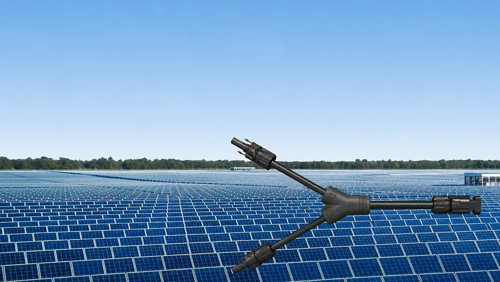
How to choose materials for your specific solar environment
Rooftop vs ground-mount
Rooftops often experience more mechanical movement and cable stress from building shifts.
Ground-mount can see different vibration profiles and moisture accumulation patterns.
Your materials selection should match the mechanical stress profile as well as weather exposure.
Coastal/saline vs dry inland sites
Coastal projects raise the risk of corrosion and conductive contamination. Prioritize:
corrosion-resistant contact metallurgy and plating,
robust sealing compounds,
housing polymers resistant to UV and humidity-induced aging.
Hot climate vs freeze-thaw cycling
Hot climates accelerate thermal aging and polymer creep.
Freeze-thaw cycles stress seals and can crack materials if they lack appropriate elasticity and durability.
Choose polymer and seal materials with durability evidence aligned to those stress types.
Conclusion: Choose materials for long-term safety, not only initial performance
When people talk about PV connector safety, they often focus on “rating” and “compatibility.” The safer mindset is materials-driven: contacts must stay low-resistance and corrosion-resistant, insulation must stay electrically robust, housings and seals must resist UV and moisture, and retention parts must maintain contact pressure under cycling.
If you treat materials as a first-class engineering requirement—and demand evidence tied to heat, corrosion, UV, moisture, and mechanical stress—you dramatically reduce the risk of field degradation that can lead to overheating and unsafe failures.
FAQ
1) What material choice affects PV connector heating the most?
In most cases, contact metallurgy and surface treatment (plating)—because they govern contact resistance stability over time. Materials that corrode or lose surface protection increase resistance and heat.
2) Are connector bodies and insulation the same thing?
No. A connector has an external housing (polymer body) and internal electrical insulation. Both involve polymer materials, but they may have different roles and must both resist UV, heat, and moisture. You should verify durability evidence for both functions.
3) How does water ingress become a safety risk?
Water ingress can reduce insulation performance through contamination, and it can also accelerate corrosion at conductive interfaces. Both pathways can raise resistance and degrade electrical safety over time.
4) Can I replace PV connector components with “equivalent” parts?
Only if the supplier confirms compatibility at the system level (materials, tolerances, sealing, termination interfaces). “Looks compatible” is not enough for safety-critical behavior.
5) What should I request from a supplier for worst-case environments?
Request evidence for: contact resistance stability, corrosion resistance, UV/polymer aging, moisture/water ingress, and mechanical retention—ideally aligned to your site conditions (coastal, high UV, freeze-thaw, high heat).

Comments